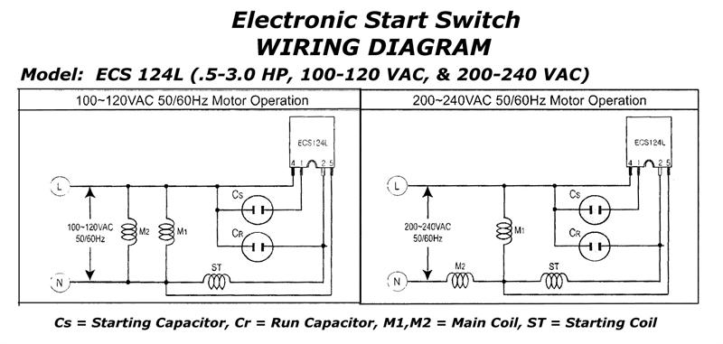
240v Electric Motor Wiring Diagram

Vt Commodore Ignition Wiring Diagram, Complete Wiring Diagrams For Holden Commodore VT, VX, VY, VZ, VE, VF, 5.36 MB, 03:54, 32,796, John Amahle, 2018-08-01T19:37:41.000000Z, 19, Vt Commodore Ignition Wiring Diagram, to-ja-to-ty-to-my-to-nasz-swiat.blogspot.com, 1272 x 1800, jpeg, bcm pcm 12j swiat nasz, 20, vt-commodore-ignition-wiring-diagram, Anime Arts
This video will show you how to wire up a 9 wire 3 phase motor to a 3 phase 240 volt system. watch till the end for my tech tip. if performing on site, be sure. Open the wiring box cover by removing the screws and verify there are four wires inside the box for wiring the motor. Look at the underside of the cover for the wiring diagram, which specifies which wires are used to wire the motor for 240 volts. Motor wire 240v wiring switch electric electrical diy stack.
Uconnect 8. 4 wiring diagram; Once the wires are stripped, use the screwdriver to loosen the screws that hold the cover plate on the air compressor. Then, remove the cover plate and set it aside. Locate the terminal block inside the air compressor and identify the power input and output terminals. The power input will be labeled l1 and the power output will be labeled l2. Wiring a 120/240 volt motor for 240 volts is as follows: A balanced electrical load which may save on electricity compared to an unbalanced electrical load. 240 volt motors will have a stronger start compared to a 120 volt motor. Longer life may be found due to a stronger motor, where as 120 volt motors may heat up more.
240V Single Phase Motor Wiring Diagram | Elec Eng World

240v Motor Wiring Diagram Single Phase | Free Wiring Diagram

240v Motor Wiring Diagram Single Phase Collection

240v Motor Wiring Diagram Single Phase | Free Wiring Diagram

[DIAGRAM] 3 Phase Electric Motor Diagrams FULL Version HD Quality Motor Diagrams - SHAREDIAGRAMS
![240v Electric Motor Wiring Diagram [DIAGRAM] 3 Phase Electric Motor Diagrams FULL Version HD Quality Motor Diagrams - SHAREDIAGRAMS](https://ricardolevinsmorales.com/wp-content/uploads/2018/09/240v-motor-wiring-diagram-single-phase-single-switch-wiring-diagram-110-single-circuit-diagrams-wire-center-u2022-rh-casiaroc-co-1q.jpg)
240V Motor Wiring Diagram Single Phase / Wiring Diagram For 220 Volt Single Phase Motor

240V Motor Wiring Diagram Single Phase - Database - Wiring Diagram Sample

240v Motor Wiring Diagram Single Phase Collection

Wiring Diagram For Single Phase 240v Motor - WORKINGMUSLIMAH

3 Phase 240V Motor Wiring Diagram | Electrical circuit diagram, Circuit diagram, Auto transformer
