5 Wire Load Cell Wiring Diagram
Vt Commodore Ignition Wiring Diagram, Complete Wiring Diagrams For Holden Commodore VT, VX, VY, VZ, VE, VF, 5.36 MB, 03:54, 32,796, John Amahle, 2018-08-01T19:37:41.000000Z, 19, Vt Commodore Ignition Wiring Diagram, to-ja-to-ty-to-my-to-nasz-swiat.blogspot.com, 1272 x 1800, jpeg, bcm pcm 12j swiat nasz, 20, vt-commodore-ignition-wiring-diagram, Anime Arts
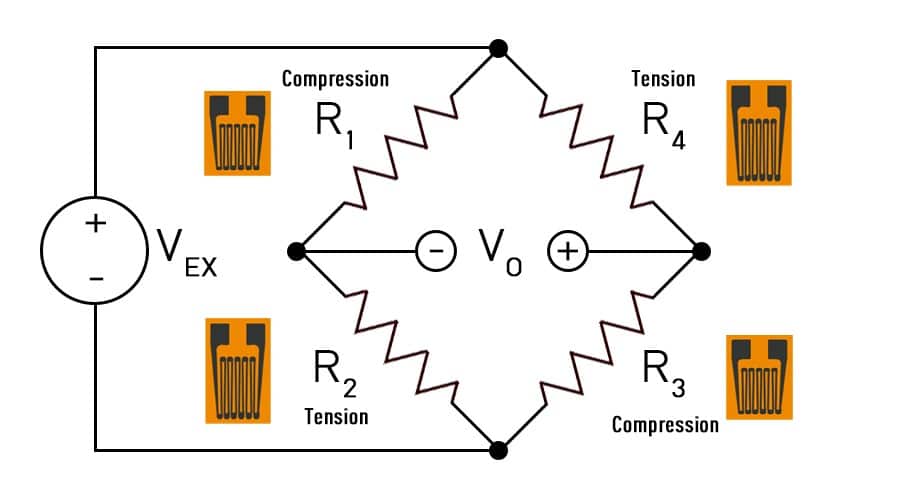
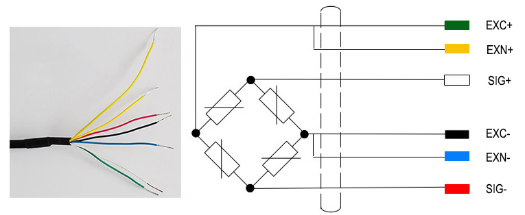
Circuit diagram mounting strain gages on load cell body pin 2 pin 3 pin 4 pin 1 sg1 sg3 sg2 sg4 view on load cell body (edge) = =. Wiring amplifier to load cell female connector. Important to know is that load cells are individuals, that is why they have an unique serial no. A couple of reasons for that are:
Thus the load cell need to be compensated individually 2. The load cell is one of the determine element for scale accuracy 3. 3 wire load cell wiring diagram from i. ibb. co. Effectively read a electrical wiring diagram, one provides to find out how the particular components inside the system operate. For instance , if a module is powered up also it sends out the signal of 50 percent the voltage and the technician does not know this, he would think he offers a challenge. The wiring diagram is made assuming the load cell is constructed like this picture. To make sure you get it right, be sure to figure out which two terminals on the load cells have the highest resistance between them (e. g. 5 wire load cell wiring diagram. Use a 1,5mm wire included for the minus connection, which should be.
Subminiature load button load cell 5kg 10kg 20kg
Technical Information - Measurement Knowledge | A&D
Load Cell Wiring Color Guide – Kmu Technoloyg Co.,Ltd.
Connection of Load cell with PLC | Download Scientific Diagram

Load cells in series - Electrical Engineering Stack Exchange
Mettler toledo Load Cell Wiring Diagram Sample

Load Cell & Force Transducer - How It Works • ANYLOAD Weigh & Measure

Load cell connection using INA 125P | AVR Freaks

Cantilever Beam Load Cell, 500kg/1000kg/2 ton/3 ton/5 ton | ATO.com

EMERGING TECHNOLOGIES: LOAD CELL AMPLIFIER
