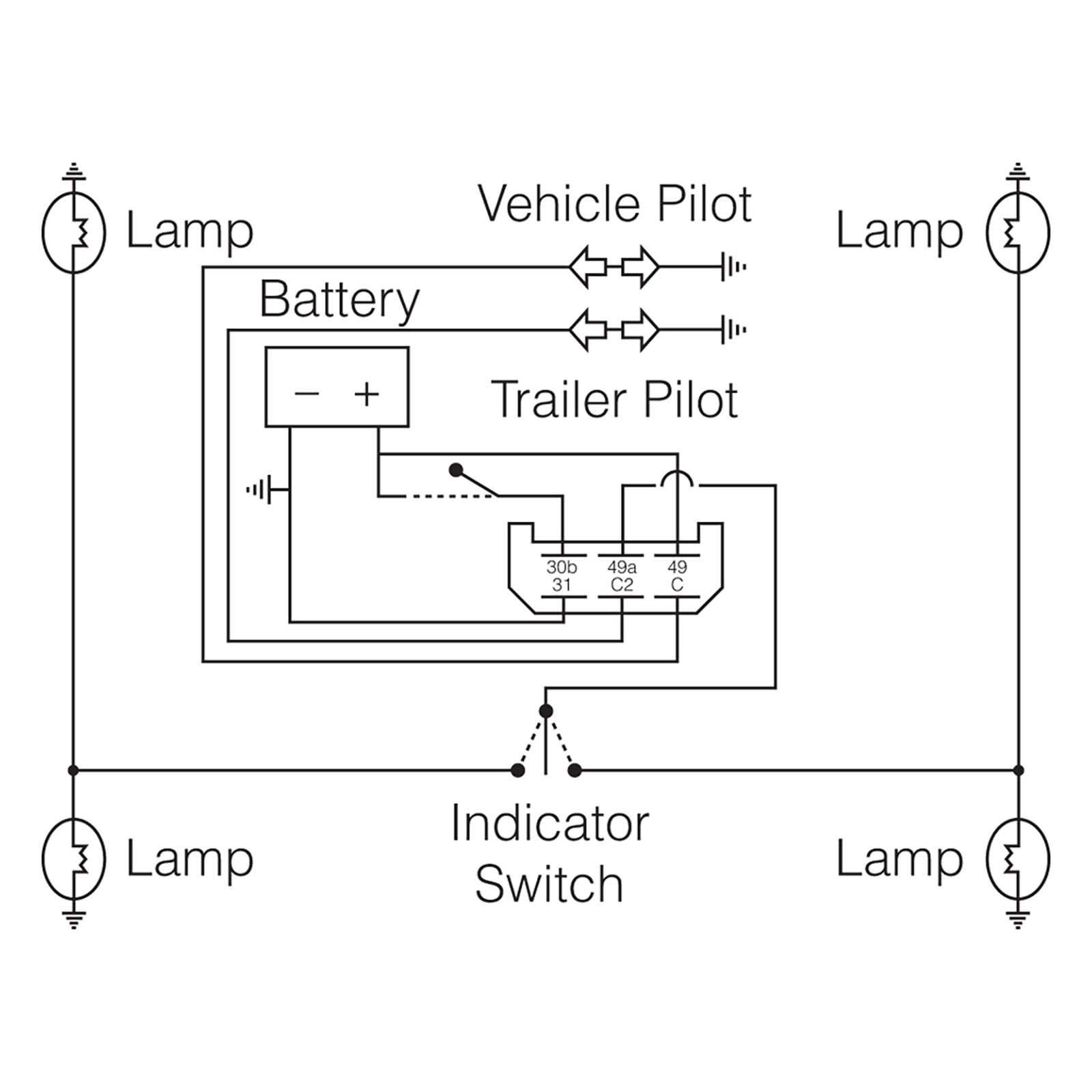
6 Pin Flasher Unit Wiring Diagram

Vt Commodore Ignition Wiring Diagram, Complete Wiring Diagrams For Holden Commodore VT, VX, VY, VZ, VE, VF, 5.36 MB, 03:54, 32,796, John Amahle, 2018-08-01T19:37:41.000000Z, 19, Vt Commodore Ignition Wiring Diagram, to-ja-to-ty-to-my-to-nasz-swiat.blogspot.com, 1272 x 1800, jpeg, bcm pcm 12j swiat nasz, 20, vt-commodore-ignition-wiring-diagram, Anime Arts
L = load, f = flasher. Be sure to ground the signal stat. Find out the newest pictures of 4 pin flasher unit wiring diagram here, and also you can have the picture here simply. In the normal (inactive) setting, the solid state relay interrupts the circuit.
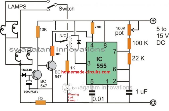
Electronic flasher unit 12v 6 pin 2 1. Installing turn signals flashers and hazards 4 pin relay wiring diagram vs 5 electronic led flasher xt500 sr500 12v fz 222sd koso 3 12 v 1 w unit 6 2 180 watt motorcycle signal sinclair c5 simplified controls ep27 flashing simple circuit with ne555 universal for 2pcs automotive gtsparkplugs vw 9 g box. I need the wiring diagram of pump it has 5 pins coming out of pump. Hello, i holding a wiring diagram central locking system,model 201,it have a 6 pin, pin no. 1 brown goes to ground; Pin. no 2 black ignition on; 3 red permanent 12 volt; 1 yellow trunk lid switch ; 2 blue driver door switch; Pin no. 3 green.
6 Pin Flasher Unit Wiring Diagram - Wiring Diagram

Wiring Diagram For Car Flasher Unit

52 6 Pin Flasher Unit Wiring Diagram - Wiring Diagram Plan

38 6 Pin Flasher Unit Wiring Diagram - Wiring Diagram Database
6 pin flasher relay wiring diagram - Google Search | Automobile | Pinterest | Cars

38 6 Pin Flasher Unit Wiring Diagram - Wiring Diagram Database

6 Pin Flasher Unit Wiring Diagram - Wiring View and Schematics Diagram

TRACTOR 12V 6 PIN INDICATOR RELAY UNIT FOR MASSEY FERGUSON FORD OE QUALITY | eBay

41 6 Pin Flasher Relay Wiring Diagram - Wiring Diagram Source Online

41 6 Pin Flasher Relay Wiring Diagram - Wiring Diagram Source Online
